This page is intended only for newbies like me [ Some of the links/images/clues may be helpful ]
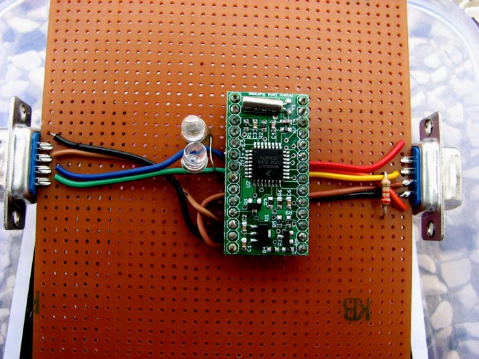
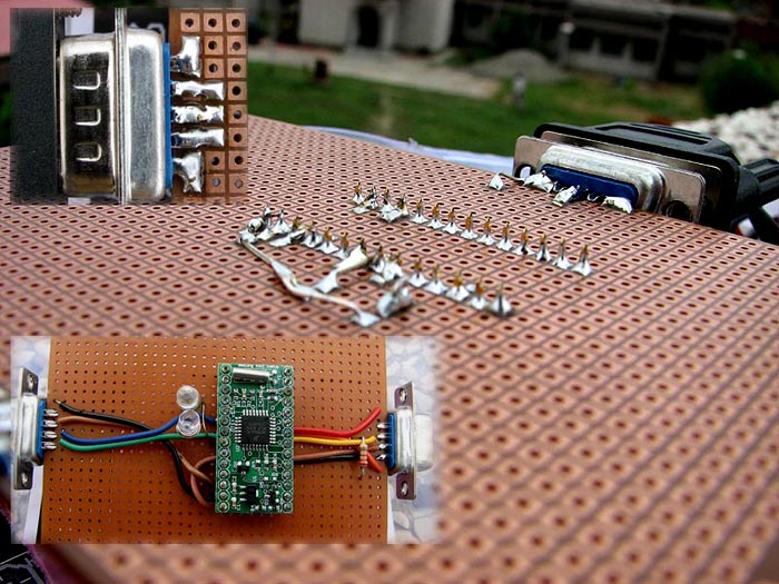
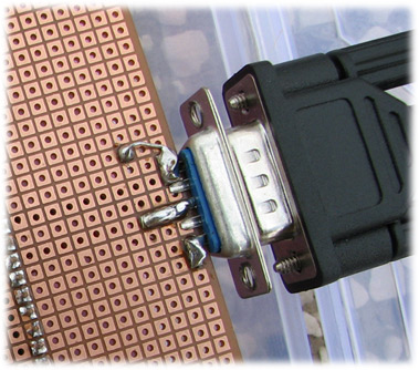
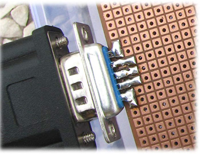
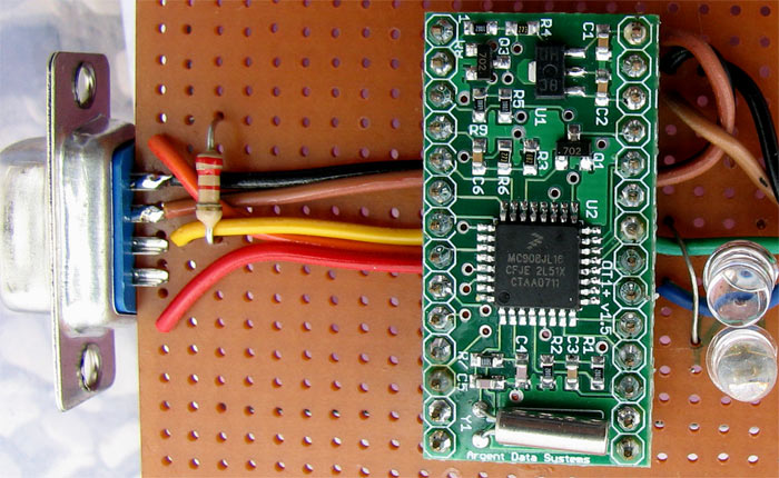
After damaging the first OT+ V1.5 SMT board, I started afresh; Ordered a new board from OM Scott, N1VG. I think my wirings are neat this time and I did the soldering a little better than the previous attempt. Now this unit is working fine with a GPS from Byonics.
Click here to see raw data for my SSID VU2MUE-11 [ Balloon simulation ] at http://aprs.fi
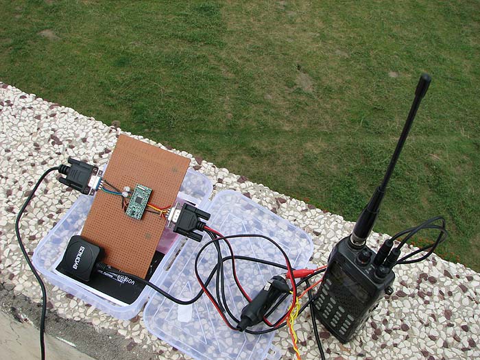
Click here for Map view [ Log-on using call-sign. Non-hams can just type any ID. No registration ]I have interfaced it to my ICOM IC W32A handy. I found that keeping the beacon rate to 180 second is a reasonable time to allow the GPS to fix.
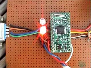
LEDs are useful!
I added the RED and GREEN LEDs too this time as they give some visual indication about whether the unit is working properly. In the first board I wired, I did not have the LEDs and I was entirely clueless what was happening.
How the LED should behave?
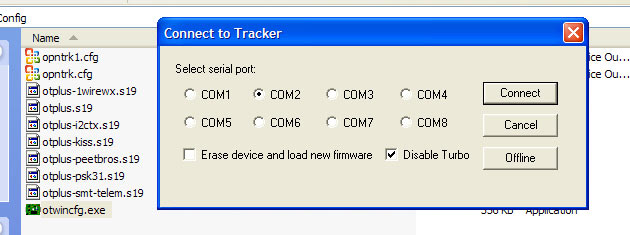
When the tracker is connected to the computer serial port [ I am not using the real serial port but a Prolific USB/Serial Adaptor which is my COM2 ] via the Null Modem [ I prefer to connect it with its power switched off ] and switch 'ON' the power, the first thing I should see is a single blink from the RED LED. Now as I run the Opentracker Configuration Application , it takes me to the following window:
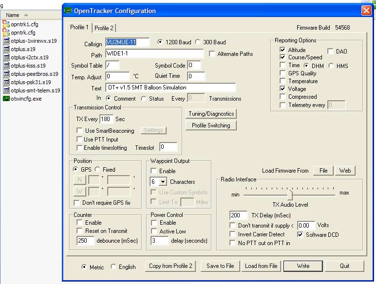
As I click 'Connect', the GREEN LED should go 'ON' and then 'OFF with a 'SINGLE' blink and after that the RED LED should go 'ON' immediately and It would remain lighted till the SMT tracker configuration software is not quitted. The Configuration window looks like [ This configuration window is if the microcontroller is written with the OpenTracker+ Standard firmware build 54568. I configured the tracker as a Balloon for simulation ]:
I give a 'space' before the Text Comment so that the Voltage information appear separated from the 'Comment line'.
Here is a video shot by me while Configuring the unit and running the diagnostic 1.04 MB
I am happy with Scott's SMT version of Opentracker+ and 'torture testing' it. During daytime, I try to keep it 'ON' whenever possible for a long time under the Sun. The +5 volt to the Byonics GPS is taken from OT+SMT board itself. I have not measured the current drawn by the GPS but have not noticed too much of heating after prolonged operation. Scott told me that this GPS may not work beyond an altitude of 60,000 feet. A Garmin GPS may work fine for near space balloons. Temperature in New Delhi is now somewhat cooling down with rains trickling frequently. Summer temperature in New Delhi goes as high as 47 degrees and sometime almost half of the boiling point of water! I sometime keep the unit on the roof of a concrete apartment. Sometime I keep it indoor [ without air-conditioner ]. There is on AC fitted in one room. So you may see abruptly fluctuating temperature. This should not be mistaken as a malfunction.
Erratic Packet Burst
I have noticed that 'sometime' there are erratic packet bursts lasting continuously for approximately 2 minutes [ the RED LED starts flickering ] which UI-VIEW does not recognize. However, this gets subside on its own and the tracker return to the normal state of TX on its own. I think this might be a problem of GPS losing the fix abruptly [ a major source of errors in a GPS fix is said to be due to transmission delays in the ionosphere ] due to some reason causing the SMT tracker to transmit unrecognizable packet bursts. Here is an informative link about GPS.
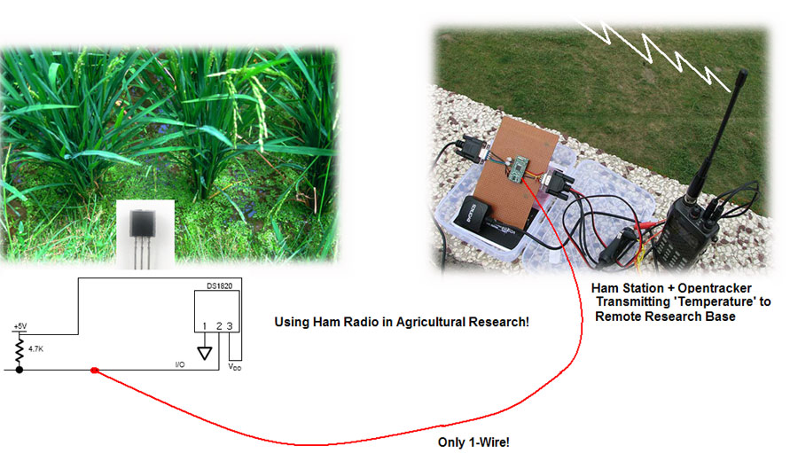
Dallas 1-Wire® Digital Temperature Sensor with OT+SMT
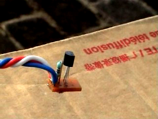
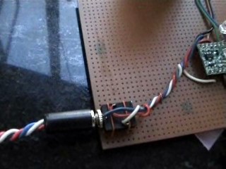
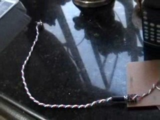
I received the 1-Wire® Digital Temperature Sensor [ It is a Dallas DS1820 ] from from Scott, N1VG on August 14, 2008. On August 15, 2008, I configured the tracker as a WX [ weather ] station by writing the Dallas 1-wire weather station support firmware to the microcontroller. I used a three pin audio jack to power the DS1820 from the OT+ itself. I can just remove it from the OT+SMT board and by providing an independent power source, can really use a single wire later.
This LED glow symbolizes my first real WX packet burst [ Only Temperature ]
Reading the packets
Here are the links archiving my WX transmissions [ Only Temperature ! ]:
Map view [ at http://aprs.fi ]
Dallas 1-Wire® Digital Temperature Sensor with OT+SMT
[ VU2MUE-2 is a Temperature only Weather Station! Temperature would depend on where he keeps the The Dallas DS1820 Digital Sensor. So don't take it for granted that the temperature displayed is the real WX ]
Raw Data [ at http://aprs.fi ]
FindU is a brainchild of American Emergency Doctor Steve Dimse -a sailor, computer geek, musician and Wild Life Conservationist. the Doctor who hung up his Stethoscope. Dr.Steve's computer is archiving my Temperature transmissions Here I can see Temp. in Degrees Celsius. Celsius' is named after a Swedish astronomer who devised the centigrade thermometer (1701-1744)
A typical packet at aprs.fi looks like:
VU2MUE-2 is one radio with the Digital Temperature Sensor+Opentracker+
VU2MUE is another radio connected to the computer+INTERNET! = this stands for position information_ = this is for WX [ Weather Icon ] as can be
seen at: http://aprs.fi/?call=VU2MUE-2 [ log-on using call-sign/name ]APRS.FI is the brainchild of a ham from Finland who is also a Computer Engineer and a Musician http://oh7lzb.blogspot.com/ ] at the same time. He recently performed at Mexico.Meaning of a raw packet
2008-08-16 06:59:30 UTC: VU2MUE-2>APOTC1,WIDE1-1,qAR,VU2MUE:!2831.64N/07708.84E_.../...g...t085OD1wMeaning of t085OD1w:
t = Temperature
085 = 85 degrees Fahrenheit [named after Daniel Gabriel Fahrenheit a German physicist who invented the mercury thermometer and developed the scale of temperature that bears his name (1686-1736)] rounded off value
O = Opentracker by Scott Miller, California [ An American ham, computer engineer and business entrepreneur
D = Dallas [ http://www.maxim-ic.com/company/dallas/ ]1 = 1W = WireIt is Radio + Internet ! !Here are some links which are informative to learn about DS1820 and its interfacing:
Interfacing a DS1820 to a microcontroller